Hemp Fingers
The hemp stripping fingers comprise of a metal stripping element backed with a composite support. Each finger comprises of 12 teeth in an 8 sided rotor.
The wider finger spacing allows for larger stalks and helps to prevent wrapping.
A modified version on the popular CVS stripper header model provides the platform suitable for harvesting hemp. Headers are available from 12ft(3.6m)- 32ft (9.6m)
The main drive for the Hemp headers is the proven variable speed drive which is used on the CVS. The CLH drive is only used for the 8ft (2.4m) headers
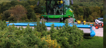
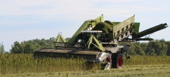
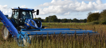
Shelbourne stripper headers have been used globally for harvesting hemp leaves, flowers & buds for a number of years. The action of the stripping rotor combs through the fibrous stalk removing the seeds, buds & leaves with little damage to the fragile crop and therefore maximizing the CBD oil content available.
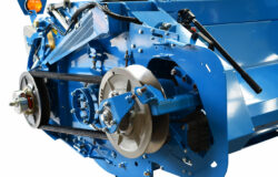
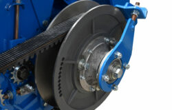
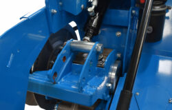
The CVS models utilize the proven variable speed belt drive system, rotor speed is adjusted with an electric actuator on the drive pulley in conjunction with a posi-torque spring tension system fitted to the front pulley.
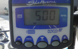
The in cab monitor allows the operator to adjust the speed of the stripping rotor by controlling an electric actuator that adjusts the drive pulley. The speed of the rotor and the auger are displayed and includes an alarm system to aid the operator.
| Heavy duty self tensioning variable speed belt |
| 3 ramp posi-torque cam with high capacity spring |
| Hydraulically actuated speed adjustment |
| 3 variable speed ranges ** |
| 430-580rpm |
| 500-690rpm |
| 660-790rpm |
| fixed low maintenance rear pulley |
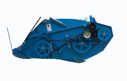
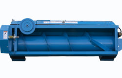

The CLH (Cereal Light Header) is only available in a width of 2.4m (8′). The drive for the rotor is via a single vee belt and the speed can be adjusted by swapping the drive pulley. The auger is also driven by a vee belt.
There are 2 options for the discharge position, either central or right hand rear of the header.
The rear of the header is supplied without enclosing the auger to allow fabrication of brackets etc to attach to the desired power unit.
A third party fabricator will be required to attached the header to the power unit and discharge system.
| 2.4m (8') width |
| Light weight design |
| vee belt drive system |
| Rotor adjusted by interchanging pulley |
| Hydraulic or Shaft input |
| RDS Monitor kit to display speeds |
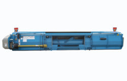
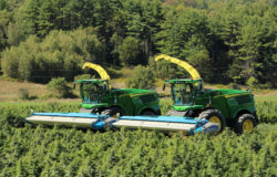
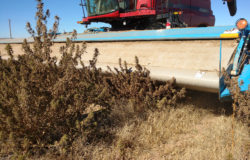
The standard stripper header adapter plate system is suited when either a forage harvester or a converted combine are used as the power unit.
| Bolt in Adapter |
| Central Feed Auger |
| Simple conversion from a standard CVS header |
| PTO Drive |
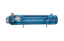
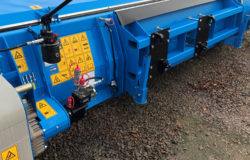
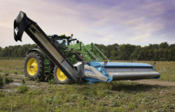
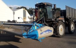
A blanking adapter it bolted in the center which can be mounted to various power units such as a loader, handler or specialist power unit (Xerion).
The discharge is via a right hand feed auger at the rear of the header.
A discharge system will need to be fabricated to move the harvested material from the header to a trailer by a third party.
The propelling vehicle must be capable of safely handling the weight of stripper header and conveyance device whilst maintain stability, especially when the stripper header is raised to harvest taller crops.
Forward visibility may be impaired depending on height of operators position and harvesting height, forward facing cameras maybe required.
| Hydraulic drive |
| Rear right hand discharge auger |
| suitable for taller crops |
| suited for various power units |
| brackets can be offset to help balance |
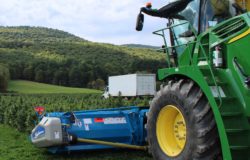
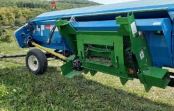
Power units such as a forage harvester or combine can transmit the power to the header via a pto shaft, a single acting hydraulic service it then required for the adjustment for the crop deflector.
| High Torque power |
| Shear Bolt Protection |
| Simple conversion from standard CVS Header |
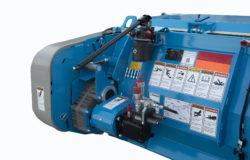
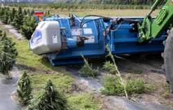
Suitable for mounting on fore end loader or handler.
The discharge is at the rear on the right hand side via a cross auger.
| Versatility with different power units / mounting system |
| Relief valve protection |
| Speed adjustment via oil flow |
| Requirement upto 100l/min at 210bar |
To operate the stripping rotor and auger a hydraulic flow of 100 litres per minute (l/m) (26.4 US gallon per minute (gpm) is required at 210 bar (3050 PSI) pressure. This will give a rotor speed range of 420-770 rpm and an auger speed of 180 rpm.
Reducing the hydraulic flow will reduce the speeds of both the rotor and auger, which in some case may be desirable. (see Hydraulic Speed Chart below).
In order to reduce back pressure, reduce heat generation and maintain the efficiency of the hydraulic system the return hose from the motor should a free flow return to tank and not go back through the tractor rear selective control valve (SCV) (spool valve).
If reversing the rotor and auger to clear a blockage the hydraulic lines will need to be interchanged to run the hydraulic motor in reverse.
Hydraulic hoses should be suitably sized for the hydraulic flow so as not to causes excessive back pressure, which can generate excessive heat and reduce efficiency of the hydraulic system. This is particularly important as a long hose may be required to connect the propelling vehicle and stripper header.
| Flow Rate | Pressure Line Hose Diameter | Return Line Diameter |
|---|---|---|
| 95 l/m (25 gpm) or more | 1" | 1" |
| 70-94 l/m (18.5-25 gpm) | 3/4" | 1" |
| below 70 l/m (18.5 gpm) | 3/4" | 3/4" |
The hydraulic motor case drain should be connected back to tank with a zero pressure return line with a diameter of 3/8” or larger, again this should be a free flow return and not be connected to a SCV.
To operate the crop deflector a single acting SCV is required ¼” diameter hoses will suffice. If the loader is fitted with an auxiliary hydraulic service this would be suitable for operating the crop deflector.
Therefore one double acting rear selective control valve (SCV) (spool valve) is required, independent of those used to control the loader capable of supplying 100 l/min (26.4 gpm) with a free flow return. The spool valves ideally want to be electronically adjustable from the cab. Plus an additional spool valve on the loader (commonly known as 3rd loader service) to operate the crop deflector. Then an additional free flow return is required for the case drain for the hydraulic motor.
In Addition an SCV and oil flow may be required for any conveyance device fitted.
| Flow Rate | Hyd Motor Speed | Auger Speed | Min Rotor Speed | Max Rotor Speed |
|---|---|---|---|---|
| 90 l/m (23.8 gpm) | 450 rpm | 160 rpm | 370 rpm | 700 rpm |
| 95 l/m (25 gpm) | 475 rpm | 170 rpm | 390 rpm | 740 rpm |
| 100 l/m (26.4 gpm) | 500 rpm | 180 rpm | 420 rpm | 770 rpm |
|
CVS Model - 37/32 Gears, 18t auger sprocket & 200cc motor.
|
||||
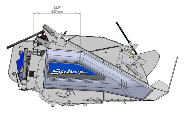
| Weight | Load Centre Forward | Centre Offset | |
|---|---|---|---|
| CHL 8 | 600Kg 1322lbs | 657mm 25.9" | |
| CVS 12 | 1600kg 3530lbs | 657mm 25.9" | 482mm 19" |
| CVS 16 | 1850 Kg 4080lbs | 657mm 25.9" | 482mm 19" |
| CVS 20 | 2100Kg 4630lbs | 657mm 25.9" | 482mm 19" |
|
Please note the addition of a conveyance device will affect the overall weight and the load centre.
|
|||
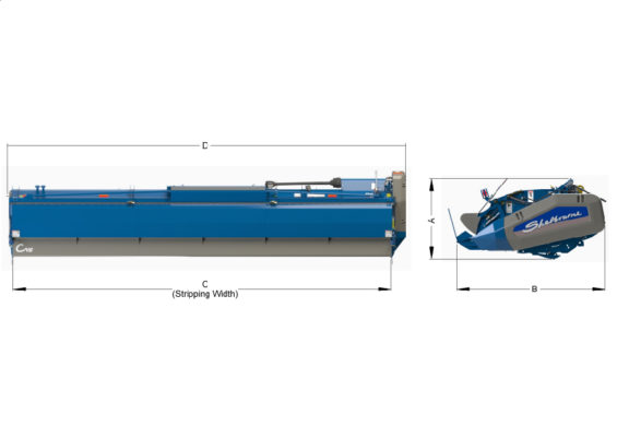
| Model | A | B | C | D | Weight |
|---|---|---|---|---|---|
| CLH 08 | 1050mm 3'5" | 2070mm 6'9" | 2400mm 7'10" | 2710mm 8'10" | 600Kg 1322lbs |
| CVS 12 | 1152mm 3'9" | 2260mm 7'5" | 3600mm 11'10" | 4036mm 13'3" | 1600kg 3530lbs |
| CVS 16 | 1152mm 3'9" | 2260mm 7'5" | 4800mm 15'9" | 5236mm 17'2" | 1850kg 4080lbs |
| CVS 20 | 1152mm 3'9" | 2260mm 7'5" | 600mm 19'8" | 6436mm 21'2" | 2100kg 4630lbs |
| CVS 24 | 1152mm 3'9" | 2260mm 7'5" | 7200mm 23'7" | 7636mm 25'1" | 2350kg 5580lbs |
| CVS 28 | 1152mm 3'9" | 2260mm 7'5" | 8400mm 27'7" | 8836mm 29' | 2930kg 6460lbs |
| CVS 32 | 1152mm 3'9" | 2260mm 7'5" | 9600mm 31'6" | 10036mm 32'11" | 3080kg 6790lbs |

Since 1972, Keith Shelbourne formed Shelbourne Reynolds Engineering Ltd, designing and manufacturing farm machinery in Suffolk, England.
Read moreBy: Shelbourne Reynolds
By: Shelbourne Reynolds
By: Shelbourne Reynolds
By: Shelbourne Reynolds
By: Shelbourne Reynolds
By: Shelbourne Reynolds
By: Shelbourne Reynolds
By: Shelbourne Reynolds
By: Shelbourne Reynolds
By: Shelbourne Reynolds
By: Shelbourne Reynolds
By: Shelbourne Reynolds
By: Shelbourne Reynolds
By: Shelbourne Reynolds
By: Shelbourne Reynolds
Notifications